शुक्रवार, 29 अप्रैल 2022

Mathematical Formulation of Voltage Stability:


Mathematical Formulation of Voltage Stability – The slower forms of voltage instability are normally analyzed as steady state problems using power flow simulation as the primary study method. “Snap­shots” in time following an outage or during load build up are simulated. Besides these post-disturbance power flows, two other power flow based methods are often used; PV curves and VQ curves. These two methods give steady-state load ability limits which are related to voltage stability. Conventional load flow programs can be used for approximate analysis.


P–V. curves are useful for conceptual analysis of voltage stability and for study of radial systems.

The model that will be employed here to judge voltage stability is based on a single line performance. The voltage performance of this simple system is qualitatively similar to that of a practical system with many voltage sources, loads and the network of transmission lines.

Mathematical Formulation of Voltage Stability

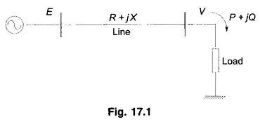
Consider the radial two bus system of Fig. 17.1. Here E is Vs and V is VR and E and V are magnitudes with E leading V by δ. Line angle Φ = tan-1 X/R and |z| ≈ X.

In terms of P and Q, the system load end voltage can be expressed as

Mathematical Formulation of Voltage Stability

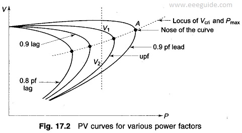
It is seen from Eq. (17.1) that V is a double-valued function (i.e. it has two solutions) of P for a particular pf which determines Q in terms of P. The PV curves for various values of pf are plotted in Fig. 17.2. For each value of pf, the higher voltage solution indicates stable voltage case, while the lower voltage lies in the unstable voltage operation zone. The changeover occurs at Vcri(critical) and Pmax. The locus of Vcri – Pmax points for various pfs is drawn in dotted line in the figure. Any attempt to increase the load above Pmax causes a reversal of voltage and load. Reducing voltage causes an increasing current to be drawn by the load. In turn the larger reactive line drop causes the voltage to dip further. This being unstable operation causes the system to suffer voltage collapse. This is also brought out by the fact that in upper part of the curve dP/dV<0 and in the lower part (unstable part)  dP/dV>0 (reducing load means reducing voltage and vice-versa). It may be noted here that the type of load assumed in Fig. 17.2 is constant impedance. In practical systems the type of loads are mixed or predominantly constant power type such that system voltage degradation -is more and voltage instability occurs much prior to the theoretical power limit.

Mathematical Formulation of Voltage Stability

As in the case of single line system, in a general power system, voltage instability occurs above certain bus loading and certain Q injections. This condition is indicated by the singularity of the Jacobian of Load Flow equations and level of voltage instability is assessed by the minimum singular value.

Certain results that are of significance for voltage stability are as under.

  • Voltage stability limit is reached when

where

  • S = complex power at load bus
  • YLL = load bus admittance
  • V = load bus voltage

Nearer the magnitude in Eq. (17.2) to unity, lesser the stability margin.


  • The loading limit of a transmission line can be determined from

Xcri is the critical system reactance beyond which voltage stability is lost. It can be expressed as

Mathematical Formulation of Voltage Stability

We have so far considered how the PV characteristics with constant load power factor affect the voltage stability of a system. A more meaningful characteristic for certain aspects of voltage stability is the QV characteristic, which brings out the sensitivity and variation of bus voltage with respect to reactive power injections (+ve or -ve).

Consider once again the simple radial system of Fig. 17.1. For Q flow it is sufficiently accurate to assume X ≫ R i.e. Φ ≈ 90°. It then follows that

Mathematical Formulation of Voltage Stability

or

Taking derivative wrt V gives

Mathematical Formulation of Voltage Stability

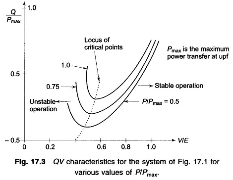
The QV characteristic on normalized basis (Q/Pmax, V/E) for various values of P/Pmax are plotted in Fig. 17.3. The system is voltage stable in the region where dQ/dV is positive, while the voltage stability limit is reached at dQ/dV = 0 which may also be termed as the critical operating point.

Mathematical Formulation of Voltage Stability

The limiting value of the reactive power transfer at the limiting stage of voltage Stability is given by

Mathematical Formulation of Voltage Stability


The inferences drawn from the simple radial system qualitatively apply to a practical size system. Other factors that contribute to system voltage collapse are: strength of transmission system, power transfer levels, load characteristics, generator reactive power limits and characteristics of reactive power compen­sating devices.

Voltage Collapse

 The process by which sequence of events associated with voltage instability leads to loss of voltage in a significant part of the system is called voltage collapse.

The phenomenon of voltage collapse is created when the demand for reactive power increases proportionate to active power. At this moment, a fully loaded transmission line generates extra inductive reactive power. Thus, capacitive reactive power from local sources becomes insufficient. Therefore, the reactive power will have to be delivered from more distant places, as a consequence transmission of more reactive power through the lines will further increase the voltage drop on the customer side. Local control of voltage by means of auto transformers will supply more reactive power, and this, in turn, will increase further voltage drops in lines. In one moment this process can go like an avalanche, thereby reducing the voltage to zero.

In the meantime, most of the generators in power plants will switch-off due to an unacceptably low voltage which of course will deteriorate the situation.

Possible Scenario of a Voltage Collapse

Possible scenario for voltage collapse are given below.

  • Generating units near load centers are out of service.
    • Heavily loaded lines having low Reactive Power Reserves (RPRs).
    • Tripping of a heavily loaded line causes load increases over other lines and loss of reactive power and voltage.
    • Load consumption would temporarily lower to stabilize. AVRs would act to restore generator voltages, but increased reactive power flow would lower voltages at consumer end or elsewhere.
    • Under the capability curve, Generators would hit Var limits.

Blackouts in a power system

A power system undergoes the voltage collapse if the post-disturbance equilibrium voltages are below acceptable limits. This voltage collapse may be converted into a total or partial blackout. A blackout in an electric system means that the complete system collapses. It originates from several causes.

Overloading of generators and transmission lines creates a deficiency of reactive power which leads voltage collapse and resultant cascade tripping can cause a blackout.

One such example is the loss of generation, e.g. the tripping of a power plant leads to overloading and under frequency over another power plant. It may result in the further loss of other generators.

Another example, is bottlenecking of transmission lines, trips other overloaded power lines, results in cascade trips. Finally, power system undergoes the voltage collapse due to high impedance in the weakened grid.

In general, one initial minor event leads to a second event, a third and so forth. Due to increased stresses on the system, it finally collapses and leads to blackouts.


Voltage Collapse: Causes and Prevention


Abstract Power system stability of large interconnected power system is the major issue the world is facing in order to obtain a secure operation of power system. Recent major blackouts across the world illustrate this issue for secure operation. Voltage collapse is the process by which the sequence of events accompanying voltage instability leads to an unacceptable voltage drop in a significant part of power system. Catastrophic decrease in voltage leads to loss of stability in large interconnected power system causing blackout. In this paper we will discuss the various causes and the prevention methods for power system collapse.


  1. INTRODUCTION

    The important operating work of power system utilities is to keep voltage within an allowable range limit in order to provide a high quality customer service. Day by day increase in power demand results in more and more pressurized transmission lines. Such systems are usually subjected to voltage instability and eventually a voltage collapse. Now-a- days voltage collapse is becoming an increasing threat to system security and stability. Power systems are expected

    to become more heavily loaded in the next decade as the demand for electric power rises while economic and environmental concerns limit the construction of new transmission and generation capacity. Heavily loaded power systems are closer to their stability limits and voltage collapse blackouts will occur if suitable monitoring and control measures are not taken. It is important to understand the mechanisms of voltage collapse so that voltage collapse blackouts may be effectively prevented.

    A.) Causes of voltage collapse

    • Increase in loading

    • Generators, synchronous condensers, or SVC reaching reactive power limits

    • Action of tap changing transformers

    • Load recovery dynamics

    • Line tripping

    • Generator outages

    Fig. 1. Potential causes of Blackout

    Fig. 2. Flow Chart for Cascading Failure Power System Model

  2. LOAD SHEDDING

    Load shedding is an option that is becoming more widely used a final means of avoiding system wide voltage collapse. This option is only considered when all other effective means of avoiding collapse are exhausted. This option may be the only effective option for various contingencies, especially if the collapse is in the transient time frame, and if load characteristics result in no effective load relief by transformer load taps changer control. Load shedding results in high costs to electricity suppliers and consumers; therefore, power systems should be designed to require such actions only under very rare circumstances. Load may be shed either manually or automatically depending on the rate of voltage drop.


गुरुवार, 28 अप्रैल 2022

Dynamic Equivalents

 Power system dynamic equivalents have been receiving significant attention since the 1970s for the purpose of reducing the computational burden and enhancing assessment efficiency. Similar to steady-state equivalents, the first step is to define the study area and the external area. In the study area, the detailed component representations are retained since dynamic performance is of direct interest. On the other hand, the behavior of the remaining system denoted as the external area is produced with an equivalent of a much lower order. It is worth mentioning that expanding the boundaries of the study system to include the main generators that have significant effect on the dynamics of the study area, will certainly improve the accuracy of any equivalent.


सुविचार

विक्रम संवत.............२०७९
मास................वैशाख
पक्ष.................कृष्ण
तिथि................त्रयोदशी
वार................गुरूवार
दिनांक..............२८-४-२०२२


🙏🏽 🌳 भारत माता की जय 🌳

सुविचार:👉 " सफलता के लिए कोई एलिवेटर नहीं है हमको अपने आप ही सीढिया चढनी होगी। "

बुधवार, 27 अप्रैल 2022

सुविचार

विक्रम संवत.............२०७९
मास................वैशाख
पक्ष.................कृष्ण
तिथि................द्वादशी
वार................बुधवार
दिनांक..............२७-४-२०२२


🙏🏽 💐 वंदेमातरम 💐

सुविचार:- " इंसान के दिमाग में
दो घोड़े दौड़ते रहते है,
एक पॉज़िटिव
एक निगेटिव...
जीतता वही है जिसे
ज्यादा खुराक दी जाए......।"

मंगलवार, 26 अप्रैल 2022

सुविचार

विक्रम संवत.............२०७९
मास................वैशाख
पक्ष.................कृष्ण
तिथि................एकादशी
वार................मंगलवार
दिनांक..............२६-४-२०२२


🙏🏽 🚩 जय सीताराम 🚩

              सुविचार
                 👇

" एक मूर्ख व्यक्ति योजना के जरिए एक बुद्धिमान व्यक्ति को भी हरा सकता है।"

सोमवार, 25 अप्रैल 2022

सुविचार

" ईश्वर बोझ देता है, और कंधे भी। "
                 👆
              सुविचार

🙏🏽 🕉️ ॐ नमः शिवाय 🕉️


विक्रम संवत.............२०७९
मास................वैशाख
पक्ष.................कृष्ण
तिथि................दशमी
वार................सोमवार
दिनांक..............२५-४-२०२२